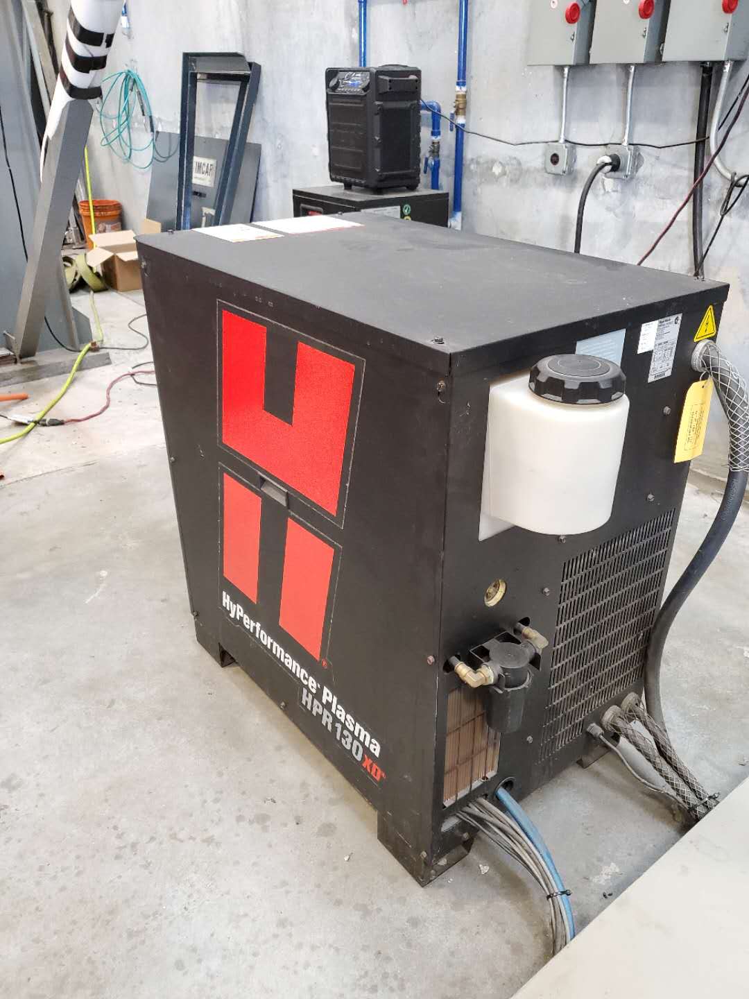
Specifications:
- Working deburring capacity: 18 Cubic Feet
- Length (overall including electric control box): 80"
- Width (overall): 60"
- Height (overall): 54"
Bowl:
- Diameter: 60"
- Cross Section: 17-1/2" (Diameter)
- Lining (Thckness of Polyurethane): 1"
Comments:
- New Style Almco Vari-Drive System
- Center Dome Feature
- Pedestal mounted control panel
- Tub 17,5" cross section
- Bowl Diameter 60"
- The machine has been cleaned and is ready to be primed and painted
Power Unit:
- 10 hp, 1800 RPM totally enclosed, ball bearing motor for 230/460 volt (please
- specify voltage), 3 phase, 60 cycle operation driving a variable pitch pulley.
- The pulley is connected to two flat V-belts in a companion sheave on the
- vibratory mechanism. Frequemcy of vibration is variable from 900 to 1400
- cycles per minute by turning the handwheel on the motor base resulting in a
- change in pulley pitch diameter. All moving drive componensts are well
- guarding for operator protection.
General:
- This High-Energy "OR" Series Machine is composed of the following basic
- compoents:
- (1) The support base and framework
- (2) The Drive Unit
- (3) Almco`s Natural Contour Molded Urethane Lined Tube
- (4) The Vertical Shaft Vibrator
- (5) The Electrical Control Enclosure
Description:
- Discharge of parts and media from the round bowl is accomplished with a plug
- type door with molding lining at one end of the bowl near the bottom periphery.
- The door is equipped with a quick-acting, overcenter cam lock that assures a
- positive seal when closed during processing. When the plug door is removed,
- the parts and media flow from the bowl onto a heavy gauge steel chute that channels them to a
- collection pan or conveyor.
- The round bown is supported on the stationary framework of the machine on
- heavy coil wound springs that serve to supplement the finishing motion of the
- bowl and at the same time to eliminate finishing vibration from the stationary
- framework.
- Finishing motion of the round bowl is accomplished by adjustable counterweights
- on the output shaft of a heavy duty vibratory mechanism equipped with self-aligning spherical
- roller bearings that are mounted in a precision machined housing. The shaft of
- the vibratory mechanism is driven by two V-belts running in a deep groove, off-set
- sheave to eliminate shock loading and whip in the V-belts. A manual lubrication
- system is provided to allow lubrication into the bearings of the vibratory
- mechanism from the stationary base.
- The machine is equipped with a water system designed to inject water into the
- processing tub. The tub is equipped with two perforated (replaceable) molded
- drain plates in the tub bottom to allow continuous flow of liquids in the vibratory
- tub.
- The electrical controls for the machine are in conformance to N.E.C. electirical
- specifications with the motor operating on either 230 or 460 volt current and with
- all operator controls on 110 volt current supplied by a transformer within the
- control box. All necessary controls for the machine`s operation including
- Automatic Reset Timer (adjustable time range) are housed in one NEMA type 12
- panel enclosure mounted on a pedestal separate from the machine to allow
- positioning the enclosure as needed.
|